Importance of Isolation Monitoring in Electric Vehicles

With the recent news of Audi E-tron recalls due to battery pack leakages, the following information on isolation is important to understand and consider.
The article talks about moisture leak into the battery pack, so the first question to ask is why does increased moisture in the pack lead to issues?
Here are a few reasons:
- Since pack voltages are high voltage DC, in the order of 400V and above, electrical isolation must be handled carefully to avoid potential leakage / shorts.
- Increased moisture can potentially create a path of low resistance for electrons to flow, thus affecting isolation of the pack which can be dangerous to the user.
The next thing to understand here is what isolation is and how is it measured
- Isolation faults can be between the positive and negative terminals, as well as from each of the terminals to chassis.
- An isolation fault between the positive and negative terminals of the battery is essentially a low resistance path between the terminals of the battery which can be extremely dangerous. We have seen tools (like wrenches or screwdrivers) being evaporated when accidentally dropped in a pack with high voltages.
- An isolation fault between a terminal and chassis could lead to leakage of current through the chassis. The chassis here being the metal body of the vehicle which is routinely in contact with passengers, emergency personnel, service staff, etc.
Now that we understand the effect of an isolation fault, lets understand how we would measure it.
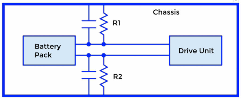
- Before we can measure isolation, we need to form a voltage reference with respect to chassis. This is done by using high (known values in the order of Mega-ohms) resistance to chassis. ce with respect to chassis. This is shown as R1 and R2 in the diagram below.
- To measure isolation, the voltage swing of the high voltage positive and high voltage negative with respect to chassis is observed. The swing is caused by switching resistances parallel to R1 or R2 one at a time. This swing in voltage lets us calculate the isolation value using the following formula as specified by the SAE standards.
An example calculation of Riso for the positive HV terminal to chassis can be done as follows -
Riso = Rswitched * (1 + V1 / V2 ) * [ ( V2 - V2' ) / V2' ]
where - Riso is the isolation resistance between the positive HV terminal and chassis.
- Rswitched is the known switched resistance in order of Mega ohms which is placed in parallel with R2.
- V1 is the voltage across resistor R1
- V2 is the voltage across resistor R2
- V2' is the voltage across resistor R2 when Rswitched is connected
To learn about isolation, and other safety related concepts for an Electric Vehicle in detail, check out our Battery Safety course.
Get started with our free 10 day course on batteries delivered straight to your email inbox!
